

IMPULSE TESTER IKD3032 Features
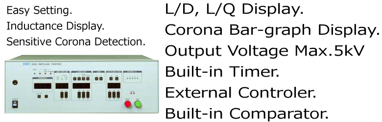
IMPULSE TESTER IKD3032 Description
This tester is adapted to test all sorts of coils such as various transformers, choke transformers and solenoids. In this tester, we got rid of the concept of waveform-measuring which has been used in conventional impulse testers, realized general tests with electric fundamental quantity by calculating of inductance and loss which are the most fundamental physical quantity of coil. This is an unprecedented new measuring method as it were a transient response type Q meter because it calculates inductance. This tester adopts innovative detecting method of corona components (patented) and displays the results as a bar graph. Thus, this tester can accurately test withstanding voltage of a coil.As this is an unprecedented high power inductance tester, this tester can provide new testing criteria for power which could not be realized by conventional testers, such as testing characteristics of a coil in saturated range.This tester can be put in an IKD's general testing equipment, and provide overall examination of a series of testing items such as withstanding voltage, insulation resistance and DC resistance.
IMPULSE TESTER IKD3032 Specifications
| Output Voltage | 0.10 to 5.00 kV 10V Step Accuracy: Less than + or - 2% of setting value + 50V (No load) |
|---|---|
| Pulse Intervals | 100mS |
| Output Waveform | Series resonance waveform of internal capacitor (0.01uF) and load |
| Output Impedance | Approx. 30 ohms 10uH (0.1kV output) |
| Measurement Range | 7 ranges: 200uH/2mH/20mH/200mH/2H/20H/200H |
| Inductance Display | 2.5 digits (199) display Accuracy: Less than + or - 5% of displayed value + 15 counts + 20uH *2 (Loss of less than 1, cable of 1.2m) *1 |
| Loss Display | 2.5 digits D (0.00 to 1.99) display or Q (0.5 to 99.9) display Accuracy: (D display) Less than + or - 10% of displayed value + 15 counts *2 |
| Corona Detection |
Bar graph display of 10/20/30/40/50% Accuracy:Undefined *3 |
| Test Frequency Display |
3 digits display Accuracy:Less than + or - 5% of displayed value *4 |
| Timer | OFF/0.1 to 99.9 seconds |
| Good/NG Judgement | 1:Setting of upper and lower limits of Inductance 2:Setting of upper and lower limits of Loss 3:Setting of upper limit of Corona Indicated by lamps and buzzer. |
| Volume of Buzzer | Changeable |
| Power Source | AC 100/120/200/240 + or - 10% 50/60Hz |
| Current Consumption | Less than 100VA |
| Weight | Approx. 9Kg |
| Accessories | Cable for Power source 3m:1 Cable for Measurement 1.2m:1 Instruction Manual:1 |
*1:
The inductance display of this tester is determined by a single test at the resonancefrequency which is determined by the internal capacitor (0.01uF) and the tested coil. Compared with other normal impedance meters this test voltage is extremely high, so the voltage value is different form the value of usual test (1 kHz, 1V).
*2:
Range 1 is excluded.
*3:
The coil value is the ratio of a peak value of corona generation voltage to the impulse voltage. But this value varies with the part of corona generation, so as a physical quantity it cannot determine the true value.
*4:
The accuracy of the standard clock is better than 0.01%, but it is degraded by errors of the analog section which captures periods.